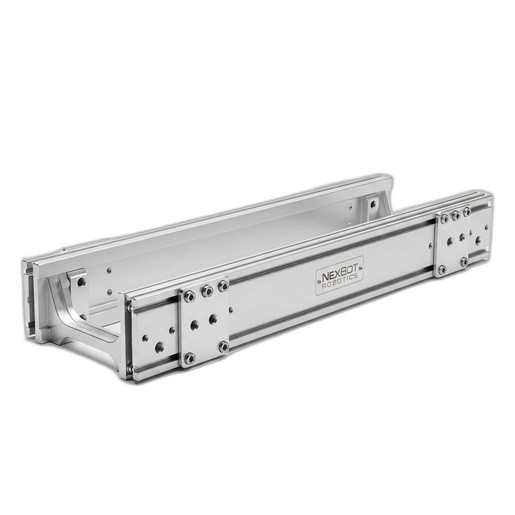
This technical bulletin provides guidelines for integrating NexBot Robotics robots with the 842-013 Conveyor Section, covering load capacity, positioning, and mounting best practices.
Related Products
Tools Required
- Spirit level or laser level
- Torque wrench
- Impact drill with appropriate masonry bits
- Socket set
- Tape measure
Article
Overview
The NexBot Robotics 842-013 Conveyor Section is a modular 1.5-meter component designed for robust material transport in automated workcells. Proper integration with robotic manipulators is critical for achieving optimal performance, reliability, and safety. This document outlines key technical considerations for system integrators and maintenance personnel when deploying the NXB-GEN-842-013 conveyor with NexBot Robotics R-Series and C-Series robots.
Adherence to these guidelines will ensure the structural integrity of the conveyor, the accuracy of robotic pick-and-place operations, and the overall longevity of the automation system.
Load Capacity and Distribution
The NXB-GEN-842-013 features a high-strength aluminum frame designed to handle significant distributed loads typical of manufacturing and assembly environments. To maximize the service life of the conveyor belt, drive motor, and frame, observe the following principles:
- Distributed Loads: The conveyor is rated for uniformly distributed loads across its surface. Avoid concentrating heavy weights in a small area (point loading), as this can cause premature belt wear or frame deflection.
- Dynamic and Shock Loads: Avoid dropping heavy workpieces onto the conveyor. The impact creates a shock load that can exceed the static load capacity of the components. Implement a smooth loading process, either manually or via an upstream automated system.
- Payload Centering: Whenever possible, place items near the centerline of the conveyor belt. Off-center loads can cause belt tracking issues over time, leading to increased friction and wear on the belt edges and guide rails.
- Total Load Calculation: When planning a workcell, calculate the total weight of all items that will be on the conveyor at any given time to ensure it remains within the system's design limits.
Robot Integration and Positioning
Precise positioning of the NXB-GEN-842-013 conveyor relative to the robot is essential for repeatable operations. This conveyor is compatible with a wide range of NexBot robots, including the R-20, R-50, C-5, and C-10 series.
- Reach and Envelope: Position the conveyor so that all required pick-and-place points are well within the robot's work envelope. Avoid programming points at the extreme limits of the robot's reach, as this can reduce accuracy and speed.
- Height Alignment: The standard height of the conveyor is 900 mm. Ensure the robot pedestal height and mounting position are selected to provide an optimal approach angle for the end-of-arm tooling (EOAT). The robot's wrist should ideally be oriented parallel to the conveyor surface during pickup or placement to minimize joint strain and programming complexity.
- Clearance: Maintain adequate clearance around the conveyor for robot movement, EOAT actuation, and potential maintenance access. Account for the full range of motion of all robot axes to prevent collisions.
- Datum and Frame Definition: Establish a precise and rigid common reference point (datum) for both the robot base and the conveyor. Use this datum to define the User Frame in the robot controller, which simplifies programming and ensures that programmed points remain accurate even if the robot is re-mastered.
Mounting and Anchoring Procedure
A stable, level conveyor is non-negotiable for reliable robotic interaction. Shifting or vibration can lead to missed picks, component damage, and system faults.
Prerequisites:
- Ensure the floor surface is clean, free of debris, and structurally sound.
- Verify that the planned location does not interfere with other equipment or personnel pathways.
Step-by-Step Instructions:
- Positioning: Carefully move the NXB-GEN-842-013 conveyor section into its designated location within the workcell.
- Leveling: Use a spirit level or laser level to adjust the leveling feet at each corner. Adjust each foot until the conveyor frame is perfectly level in both the direction of travel and across its width (500 mm dimension).
- Anchoring: Once level, mark the positions for the floor anchors through the designated mounting holes in the feet.
- Drilling: Move the conveyor aside and drill holes for the concrete anchors or other appropriate fasteners for your floor type.
- Securing: Reposition the conveyor, align the feet with the drilled holes, and install the anchors. Tighten the anchor bolts to the manufacturer's specified torque value. Do not overtighten, as this can damage the anchors or the conveyor feet.
- Verification: After anchoring, re-verify that the conveyor is still level. Make minor adjustments to the leveling feet if necessary. Confirm that the conveyor is rigid and does not rock or vibrate when force is applied.
Fixturing and Part Presentation
Consistent part presentation is crucial for vision-guided and non-vision robotic applications.
- Use of Fixtures: For parts with irregular shapes or those requiring precise orientation, use custom fixtures, pallets, or nests mounted directly to the conveyor belt. This ensures that every part is presented to the robot in the exact same location and orientation.
- Lane Guides: For simpler applications, adjustable side rails can be used to guide parts along a consistent path on the conveyor.
- Conveyor Stop/Indexer: Integrate a pneumatic stop or an indexing mechanism controlled by the robot or PLC to ensure parts stop at a precise, repeatable location for pickup.